Merging the gap between Optical and Mechanical Engineering

Providing aligned analysis and design
OnAxis Engineering logo with red sunburst icon
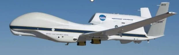
NASA remotely piloted Global Hawk aircraft flying against a clear blue sky
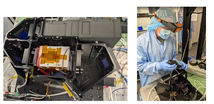
Technician in protective cleanroom gear assembling a compact scientific instrument beside its open black housing and internal components
  • Optical Design

  • Detailed Mechanical Design

  • Optical Instrument Development

  • Opto-mechanical Design and Analysis

  • Finite Element Modeling

  • STOP Analysis

  • Optical Alignment Procedures

  • Development of Flight Hardware, GSE, Alignment Fixturing

  • Stray Light Analysis

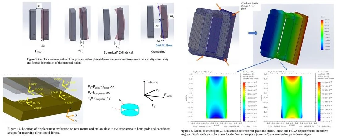
Composite engineering diagrams showing plate deformation modes, finite-element mesh displacement analysis, coordinate systems, force components, and strain-displacement contour plots for an elastic mount.
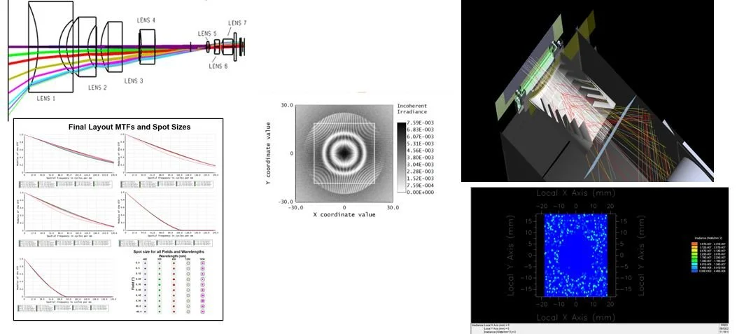
Optical lens system diagram with ray tracing, MTF and spot-size charts, interference pattern, and 3D light distribution plots
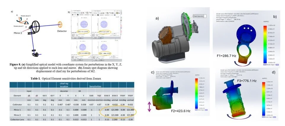
Collage of optical sensitivity analysis and finite element vibration mode simulations for a mirror and lens assembly, including Zemax spot diagrams, sensitivity table, CAD model, and resonant frequencies.
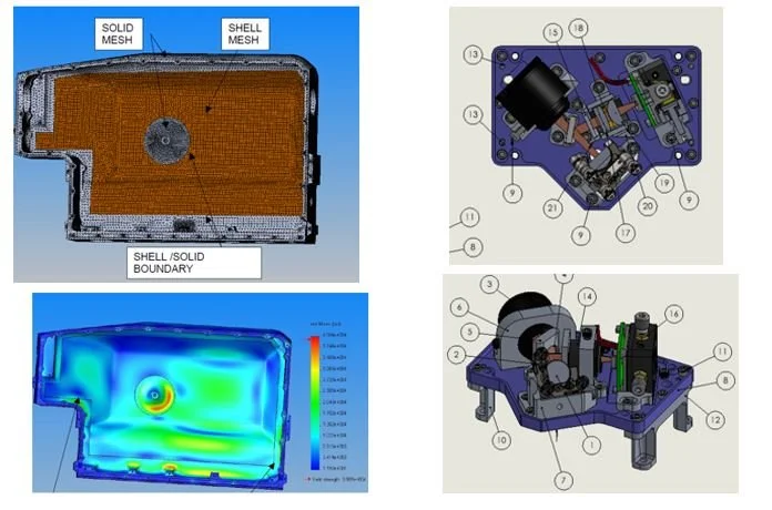
Four-panel engineering illustration showing a mesh-mapped enclosure, thermal simulation heat map, and labeled 3D mechanical assembly views.

Reach out to discuss your project

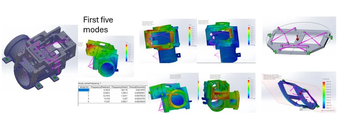
Finite element modal analysis collage showing a meshed mechanical housing, first five vibration modes, color-coded stress or displacement results, and frequency data.